N5DUX's 2m Tape Measure Yagi Antenna Page

If you're building more than one antenna,
use the Parts Calculator below.
Materials
- 1" steel tape measure - similar to Harbor Freight #62462 or Harbor Freight #62464 (just be sure it's metal!)
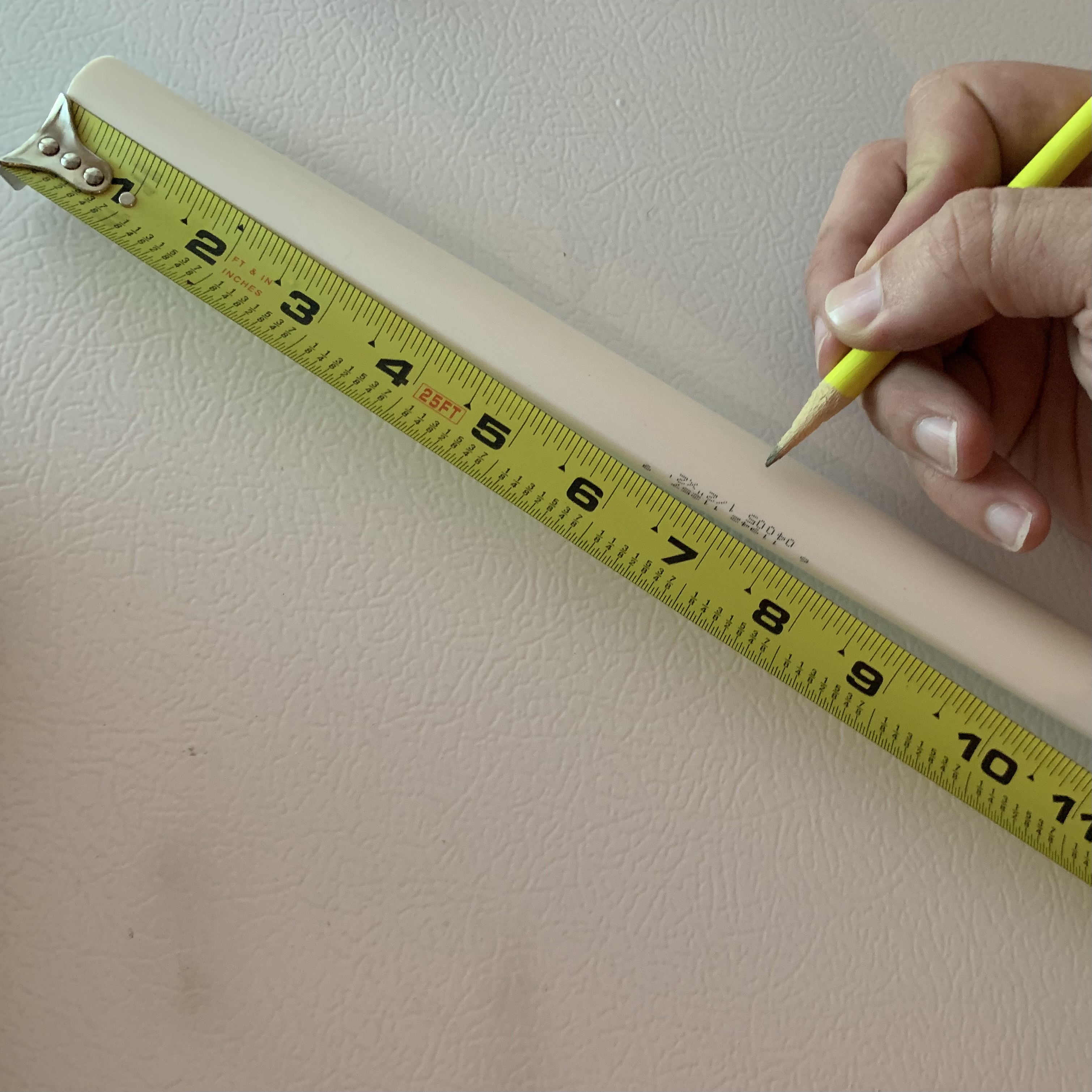
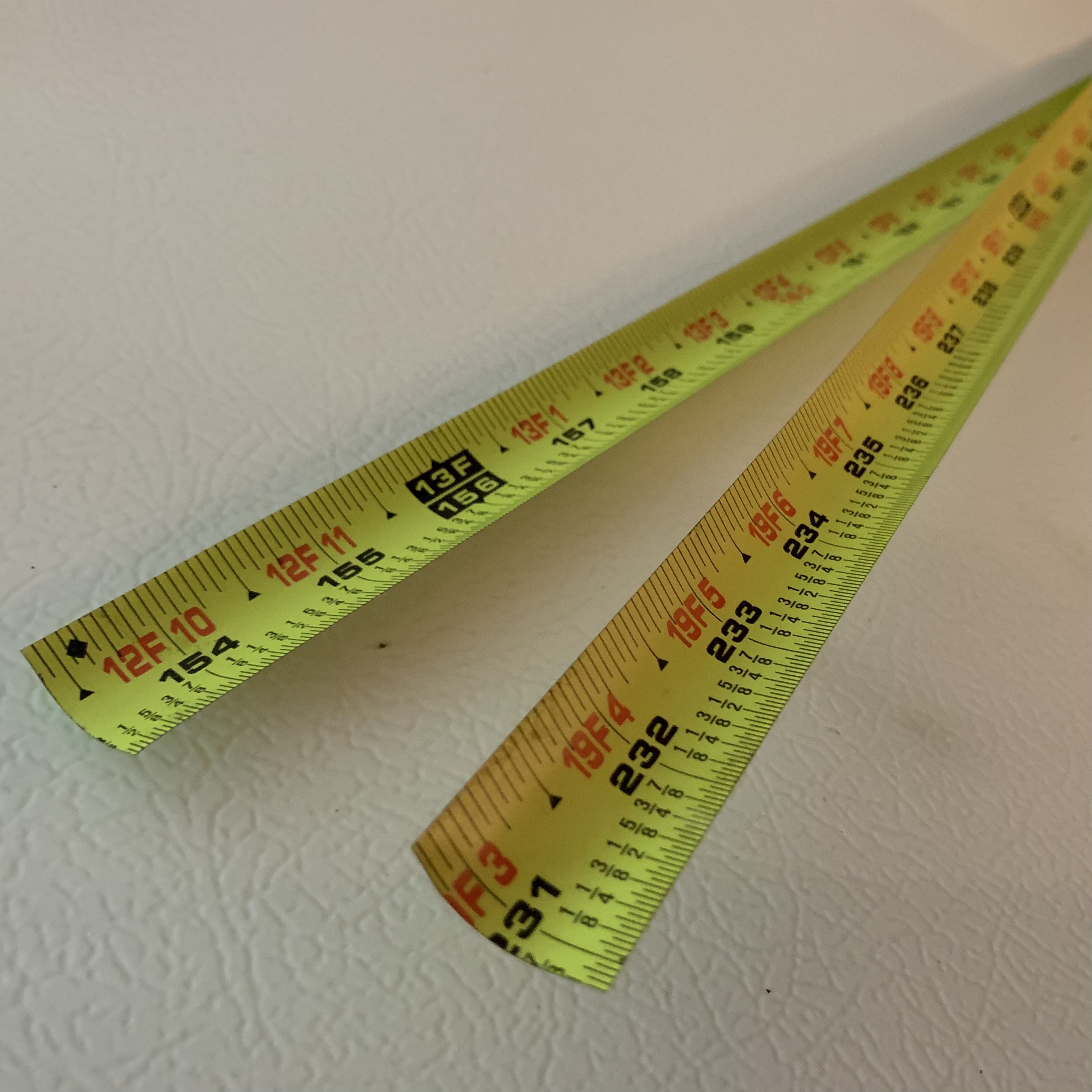
You will cut the tape measure to create:- 41-3/8" length
- 35-1/8" length
- two 17-3/4" lengths
- 1/2" PVC pipe - 2ft length - Lowes #351125 or 2ft length - Home Depot #253755
(for group builds, use 10ft length - Lowes #23966 or 10ft length - Home Depot #530048)- 11.5" length of 1/2" PVC pipe
- 7" length of 1/2" PVC pipe
- 3"+ length of 1/2" PVC pipe (leftover scrap used for handle)
- 1/2" PVC Tee Fitting - (Lowes #23873 or Home Depot #187909)
- 1/2" PVC Cross Fitting - (Lowes #24087 or Home Depot #795976)
- 6 × 1.5" hose clamps - (Home Depot #602046 or Amazon)
- ~5" of 14-18awg sold wire - I scrounged mine from some left over Romex, but stores sell it by the foot (Lowes #72517 - just be sure it's solid)
- 50-ohm coax - I use 50Ω BNC cables cut in half (Amazon single or 10pk Amazon)
(others use RG174 with SMA connectors which does not require an adapter (see below)) - 2 zip ties - for securing coax to PVC (Harbor Freight #60257)
- SMA-to-BNC adapter (if needed) - (Amazon) - This is only needed if you use BNC cable and your radio does not use BNC
Tools needed
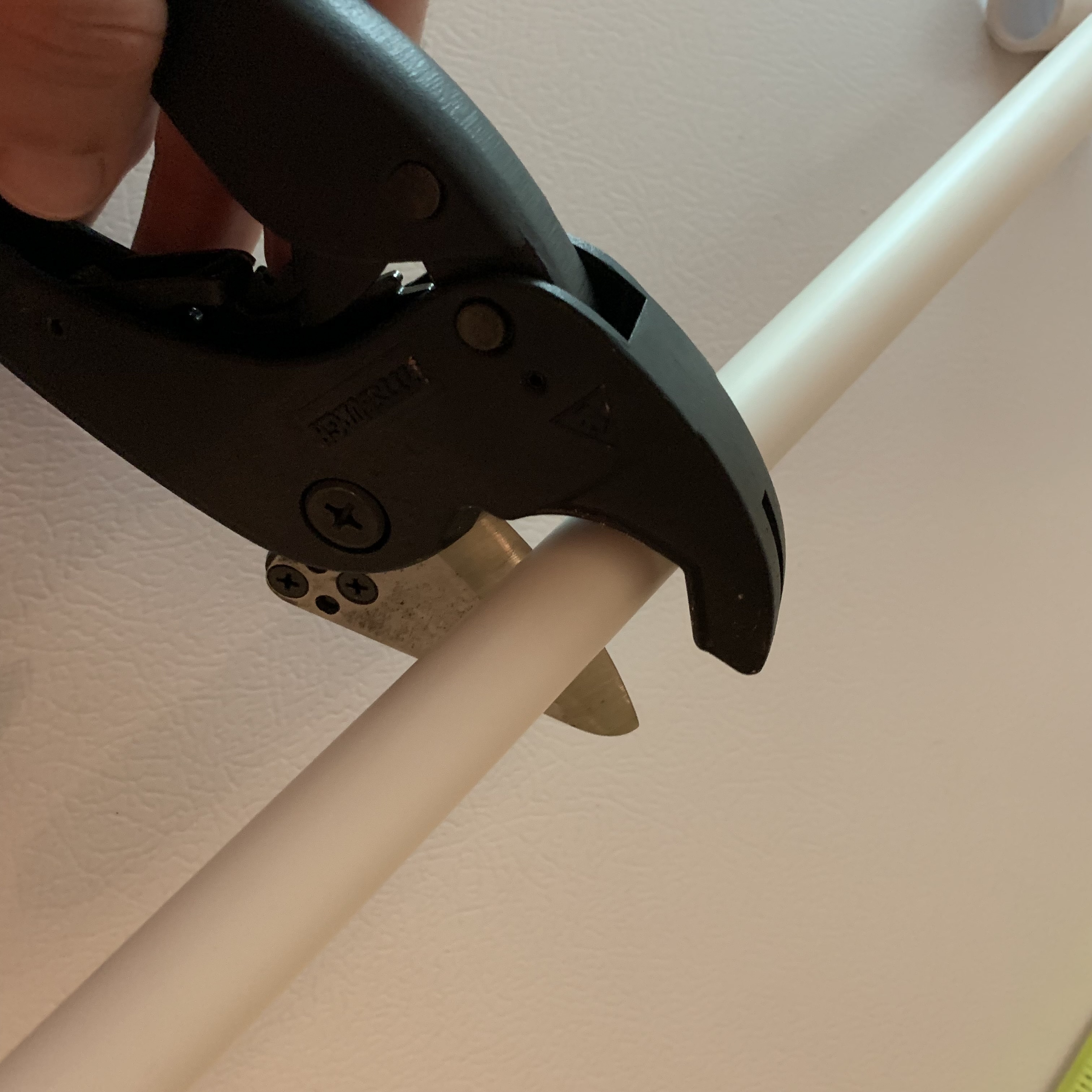
- PVC cutters (HF #62588 or HD#1003002231) or saw
- Solder (Amazon)
- Brush on flux (optional)
- Sandpaper
- Wirecutters (lineman pliers?)
- Scissors or Aviation Shears or Tin Snips
- Box cutter or coax stripping tool
- Screwdriver or nut driver (for hoseclamps)
- Roll of duct tape or electrical tape (for covering sharp ends of elements)
- KC0NFB says to use Plasti Dip (Amazon, Home Depot #202196703, or Lowes #42849) to coat cut ends of elements. This protects user and gives more "grip" when storing elements folded back into PVC cross members
- Antenna Analyzer (if available)
Construction
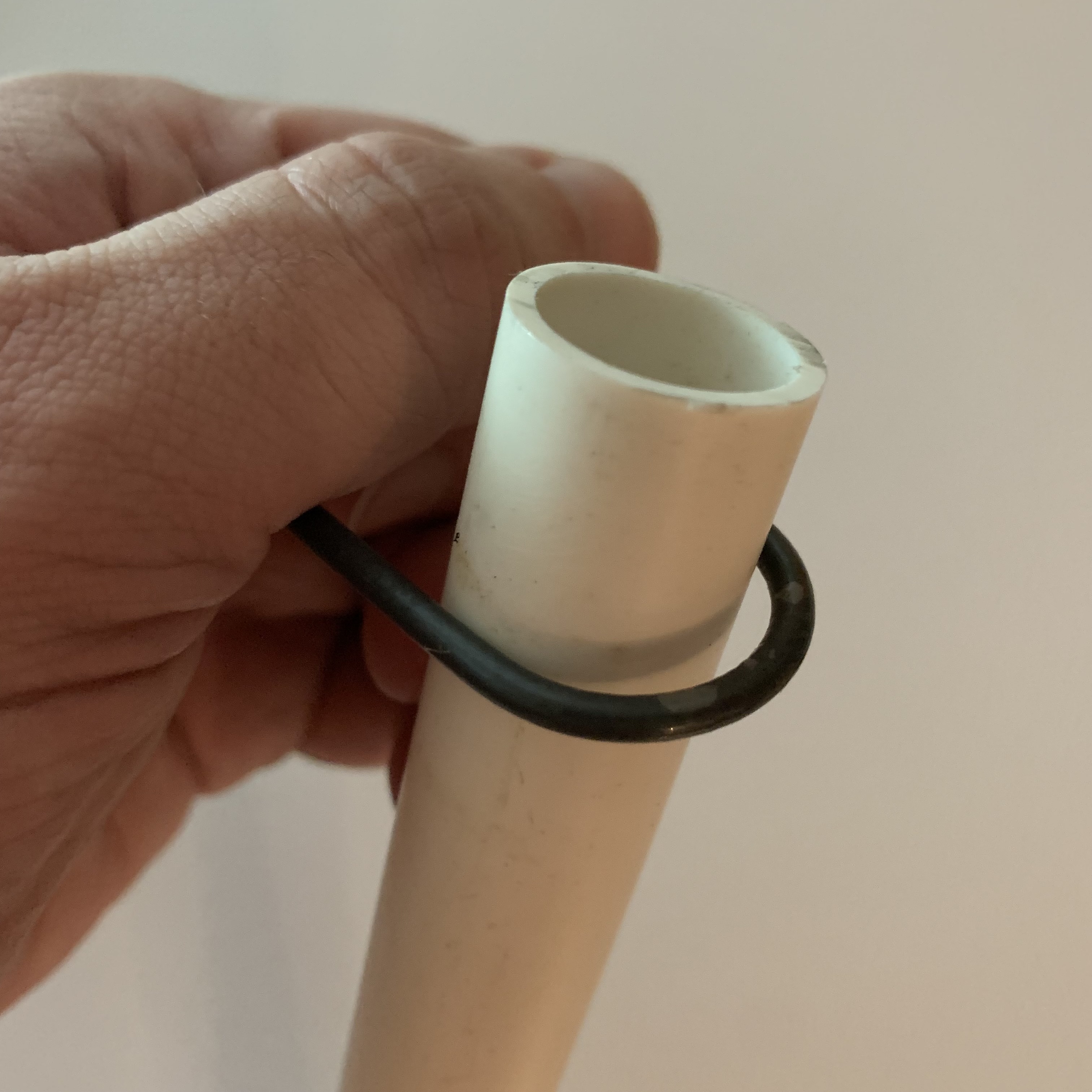
1. Measure the lengths of PVC you will need for the mast:
If you purchased a 2ft section, you should have ~5.5" left over. This will make a fine handle for final assembly. |
 |
| 2. Using PVC cutters or a saw, cut the PVC to length. A saw will suffice but PVC cutters will cut more cleanly. If cutting a lot of PVC pipe for a group, consider using a chop saw or compound mitre saw. |
 |
| 3. To cut the lengths of the tape measure there are two ways to accomplish this: you can fully extend the tape measure to the very end and unhook the "blade" from the spring retraction mechanism or have a friend hold the tape measure after each section is cut. You will need to ensure the tape measure will not retract back into the housing or it will be a pain to get it back out. Be careful of sharp ends after you cut the tape measure! Using some old scissors or aviation snips, cut the tape measure so you have a 41-3/8" length and a 35-1/8" length. These will be the reflector and director elements. Set these pieces aside for now. For the driven element, cut two 17-3/4" lengths. Set these pieces aside for now. Be careful of sharp ends after you cut the tape measure! |

 |
| 4. Using a piece of sand paper, sand away any paint from the curved (convex) bottom side of the tape measure. This will be the feed point where the feedline and hairpin match get connected. To help the driven elements lay flat later, trim the corners of the sanded tip at ~45° angle. |
 |
| 5. If you have some flux, brush on a small amount of flux to the bare metal. Put a small amount of solder on the tape measure. This will "tin" the tape measure and make it easier to attach the other components. (If the flux you used is acidic, be sure to rinse away or neutralize any excess flux.) |  |
| 6. Form the hairpin match using the solid wire. If your 5" piece of wire is insulated, remove about 1/2" of insulation from the wire. Find the center point of the wire. Place the wire over a piece of the PVC pipe and bend the wire into a U-shape. The PVC pipe will give a good, uniform bend to the wire. Brush a small amount of flux on the tips of the hairpin match then tin the ends with a small amount of solder. This will make it easy to attach to the feedpoint later. If building with a group, a solder pot will make quick work of this step. |
 |
| 7. Lay the drive element pieces curved side up and tip to tip with about 1/4" to 1/2" gap between them. Lay the tips of the hairpin match on each element and apply solder. Be sure the connection is secure. |  |
| 8. Take one PVC cross and lay the driven elements so the curve aligns to the curve of the PVC cross. Slide a hose clamp from each end of the tape measure and slip over the PVC cross. Tighten the hose clamps to hold the elements in place. | |
| 9. Assemble the director. Locate the shorter director piece of the tape measure. Lay the curved side atop the PVC tee. Slide a hose clamp from each end of the tape measure and slip over the PVC tee. Tighten the hose clamps to hold the director in place. |
 |
| 10. Assemble the reflector. Locate the longer reflector piece of the tape measure. Lay the curved side atop the PVC cross. Slide a hose clamp from each end of the tape measure and slip over the PVC cross. Tighten the hose clamps to hold the reflector in place. You may notice the tape measure flexes or buckles after you tighten the hose clamps. This is because of the crossing PVC channel in the connector. To compensate, others have used snips or scissors to cut a small rounded notch in the tape measure. If you do this, be sure not to cut through the element. It should be one continuous piece. Whether you do this modification or not, it is just for looks - it will not affect operation of the antenna. |

 |
| 11. Make the feedline. Find the center of the 50Ω cable and cut it in half. Strip the cut end of the cable to expose 1/2" to 1" of conductor. Tin the ends of the center conductor and the shield. |  |
| 12. Solder the feedline to the feedpoint. Attach the center conductor to one side of the feedpoint and the shield to the other side of the feedpoint. Be sure the hairpin match does not come loose when doing this. |  |
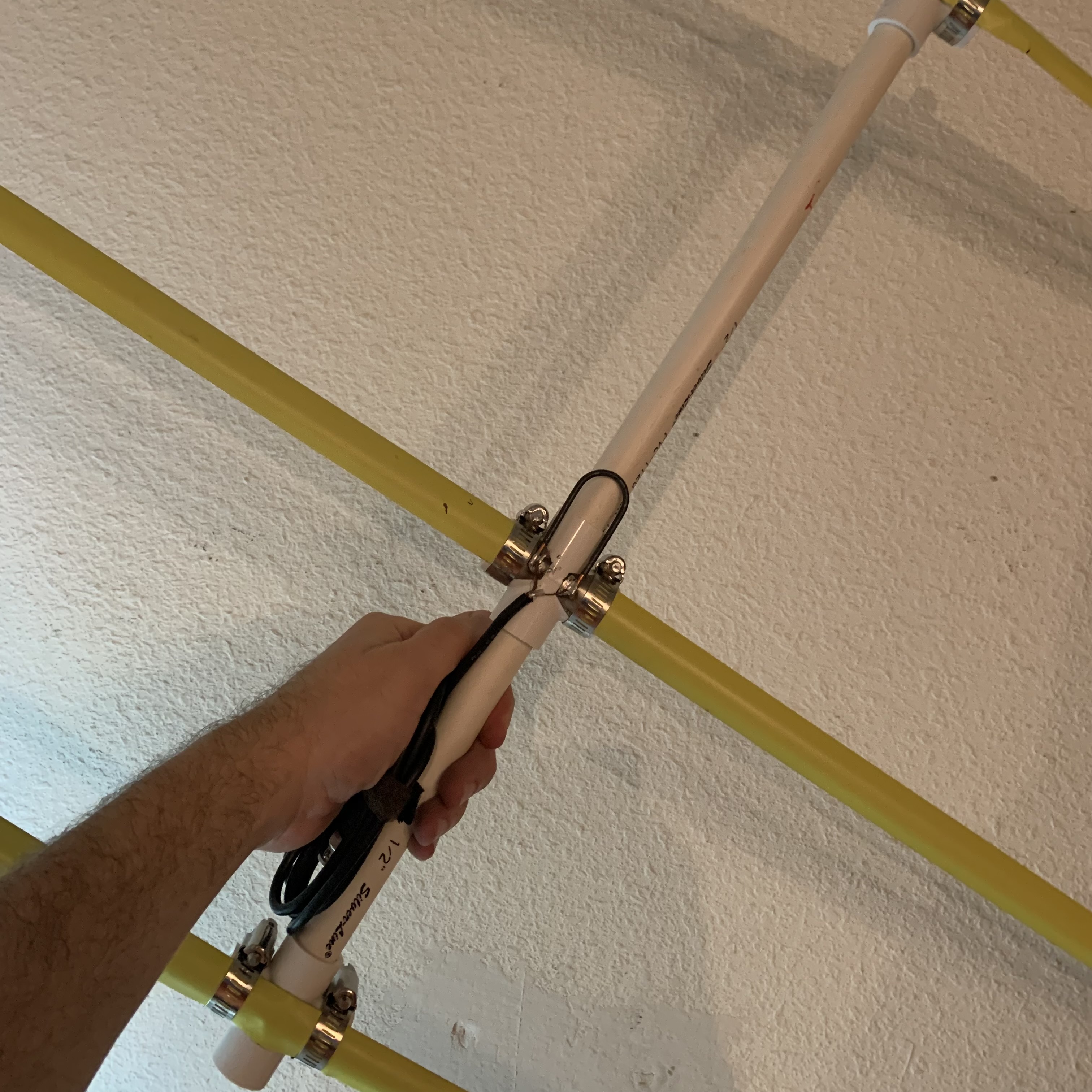
| 13. Assemble the PVC mast. Locate the 11.5" PVC section and attach the director element Tee to one end. Slip the other end of the PVC pipe into the driven element cross piece. The hairpin match should clear the boom, just be mindful when attaching it. Locate the shorter 7" length of PVC pipe and insert one end into the feedpoint cross. Insert the other end of the PVC into one side of the reflector cross. |
 |
| 14. Using a scrap piece of PVC pipe, insert a handle into the back side of the reflector PVC cross. Any piece of PVC that is 3" or more will suffice. | |
| 15. Use a couple of zip ties to secure the feedline to the PVC boom. This will act as a strain relief so you do not accidentally pull the coax loose from the feedpoint. Cut off any excess length of zip tie that remains. |
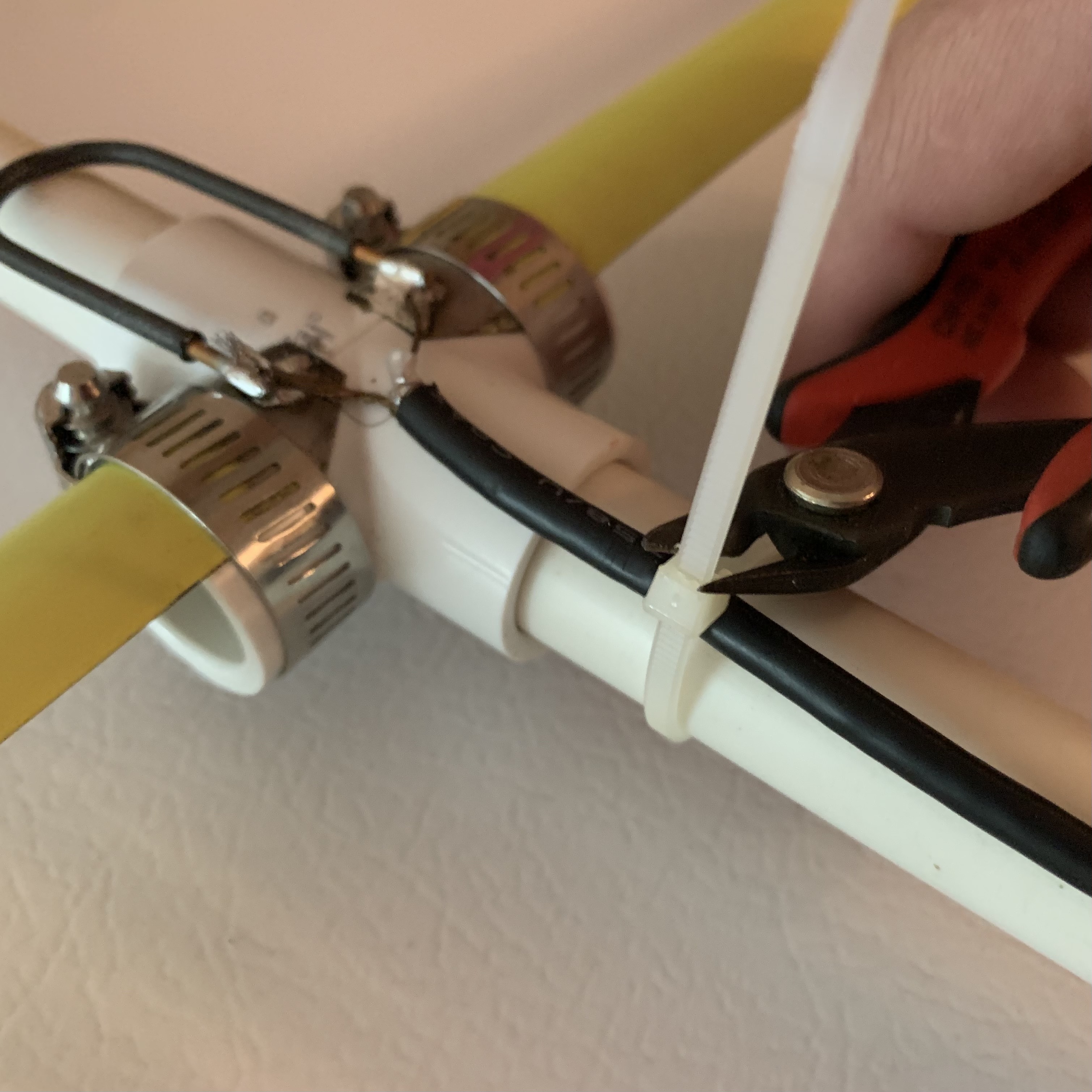 |
| All done! To keep the feedline organized, I keep a velcro scrap around it. Some fun VHF frequencies to listen for: Check a site like n2yo.com for when these will be passing over your location! |
 |
Parts Calculator
To figure out how much of each part you'll need, I've made this little calculator.Number of antennas to build: